


The Lofrans X2 windlass installation
Time for change
After hauling in my 16 kg anchor with 8mm chain by hand for 12 years, it was time to finally install an electrical, horizontal windlass on the foredeck. After looking into what other Monsuners had made their first choice, I decided to go for the Lofrans Project 1000 model X2. It is a 12 Volt version with 1000W engine and chainwheel for 8mm chain or 14mm three-stranded cable.
Choice of placement
Since I already have a bow-roller just to starboard of the foresail-roller, it was dependent on this placement where to put the windlass. The place to put it was carefully chosen by lining up the chain on deck, running it in a straight line from the bow roller to the line marked on the windlass template. And as it turned out, it can be placed right behind the bulkhead in the back-end of the chain locker. In that way, the electrical parts and motor all can be placed inside the dry forepeak, while the chain will drop in the deepest part of the chain locker. See the pictures above and below for the exact placement.
Installation of the deck hardware
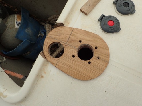
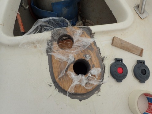
I cut away the heightened side of the chain locker for a short distance and leveled the deck a little. Then drilled the holes for the windlass bolts. After setting the ground plate, cut from 7mm plywood, over the holes I marked the 65mm holes for the axle and chain. The pencil line on the plywood disc indicates the front of the bulkhead.
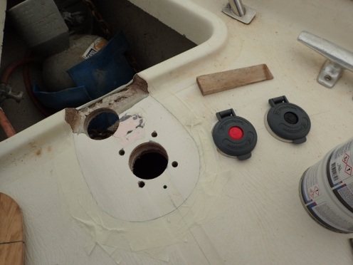
Then the holes were cut through the deck with a 65mm hole saw. The forward hole slanted at a 45 degree angle into the chain locker.
To get the windlass in line with the top of the chain locker lid, it needed to be lifted 35mm from the deck-level. So I cut a 25mm bottom plate out of a piece of teakwood. See the picture. And setting the 7mm plywood ground plate in epoxy up to a height of 10 mm from the deck (leveled horizontally), the whole thickness added up to 35mm.
These wooden parts were glued in place with epoxy resins. To prevent epoxy from spilling down in the holes I covered the holes with plastic wrap that was easy to remove after the resin had hardened.
Last thing to do was to bolt the whole construction through the deck, following the instructions in the manual. I replaced the standard M8 pin bolts with ones that were 100mm long. The originals were too short for the thickness of the deck and both plates.
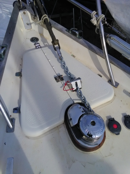
The 60m 8mm chain fit nicely in the chainwheel and falls down smoothly in the locker. In case I have had a lot of chain out, it may pile up under the windlass when retrieving it. Then, I push the pile over by hand.
Shaping the chain locker lid
Since I have a 6kg gas bottle in the front of the chain locker and the chain runs over the top of the locker lid, I wanted to be able to open the lid even when the windlass was in operation. Also, I could not close the hole to the locker more than the present size opening, because that would make it impossible to lift out the gas bottle.
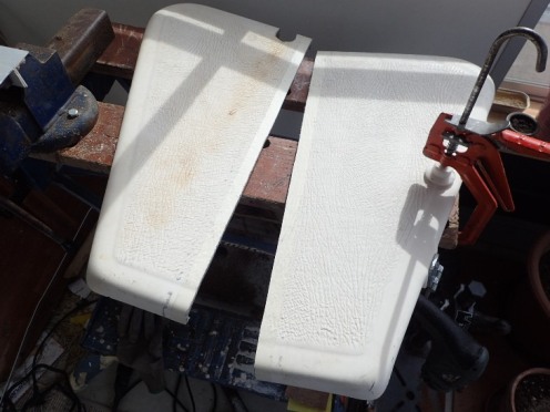
Therefore, after a lot of different ideas, I decided to cut the lock in two equal halves. Each half with its own two hinges on the outer edge. And in between the halves I made an aluminum strengthening strip (on the bottom of the starboard lid).
The original locking bolt was thereafter placed on top to hold the lid halves together and closed.
Under the starboard half-lid I strengthened the construction with a wooden plank 95mm wide and 35mm thick, through which I bolted the chain locking device that I invested in (see top picture). Two sliding locks attached to the bottom of the wooden plank keep the lid in place. Must be a strong construction, because when the windlass pulls there is a lot of strain.
Installation of the electrical parts
Below deck, I drew 2 copper cables with diameter 25mm2 from the starter battery to the connector box in the forepeak. On the positive (+) cable I put a 135A manual fuse directly after the battery connector. It sits on the wooden floor under the navigation table.
The cables where attached under the bottom of the starboard shelves, running all the way to the front of the forepeak (where I also have shelves on either side).
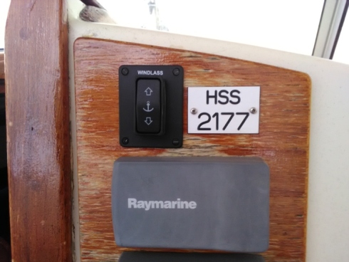
Another set of cables was running from the control buttons in the cockpit (see picture) to the connection points for the up and down switches on the control box. This was just thin copper cable.
Right next to the windlass, on the starboard side, I put two foot switches for the up and down controls on the deck. These were just small holes drilled through the deck and the holes were lined with epoxy resin.
All of the control units get electricity through a 7.5A fuse and an on/off switch on positive (+) side at the navigation table control panel.
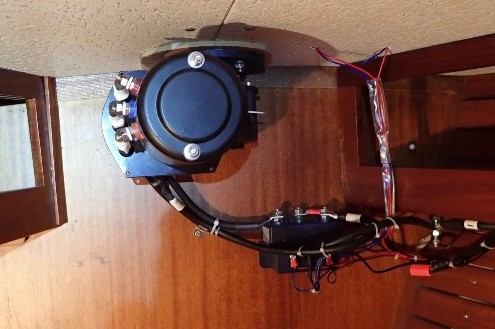
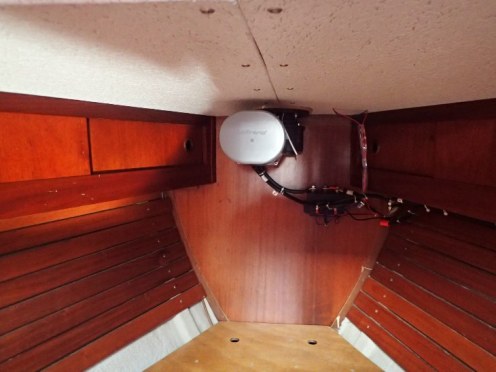
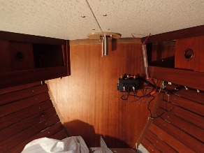
The control box was installed on the bulkhead inside the forepeak, just a short distance from the windlass motor.
Finally, cables were connected and the cover placed over the motor of the windlass. Now we are in business. So far it has been a delight to have this windlass on board.
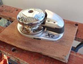
The Lofrans electrical windlass fitted on a 25mm teak base.
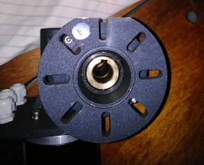
The Lofrans electrical windlass metal foot needed to be cut on the front side.
The windlass in place on the deck. Here a view from underneath.
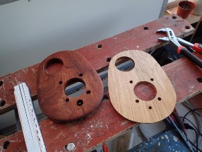
The windlass needed to be raised 35mm over the deck height. Here are the two filler plates I made.
© Johannes C. Knulst, 2008-2025
From January 2019 this site is upgraded with PHP-version 7.3 and MYSQLi compatibility.
SV Isabell is an excellent long-range sailing vessel for single handed sailing or small family expeditions. Safe, sound, and well built. With a D/L ratio of 342 this 31-foot boat gives a comfortable ride, wherever you sail.
